Electronic Components Supplier | Transformers, Inductors, Inverters

Manufacturing oil immersed transformers is a complex industrial process that requires special materials, equipment, and a high level of technical expertise. Due to the involvement of high voltage, heavy materials, and safety risks such as fire, electric shock, and environmental hazards, this is definitely not a project that amateur enthusiasts or family workshops can try.
However, understanding its manufacturing process is very interesting and valuable for engineers, students, and technology enthusiasts. The following is a detailed manufacturing guide step-by-step in a professional environment.
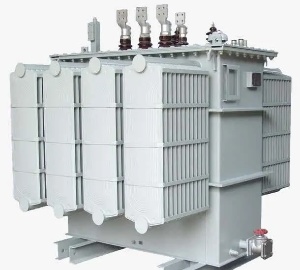
oil immersed transformers
Primary critical safety warning
Fatal high voltage: Transformers operate at lethal voltages.
Fire hazard: Transformer oil is flammable.
Environmental hazards: Improper handling of oil products can pollute the environment.
Heavy machinery: Iron cores and coils are extremely heavy.
For professional environments only: This process is only applicable to qualified personnel in controlled industrial environments.
Manufacturing Process: Step by Step Guide
The entire process can be divided into four main stages: iron core and coil assembly, oil tank manufacturing, oil treatment, and final assembly and testing.
1.Phase 1: Assembly of iron core and coil (“active part”)
This is the heart of the transformer.
1.1Iron core manufacturing:
Material: The iron core is made of thin, high-grade silicon steel sheets laminated together (usually with a thickness of 0.23 mm to 0.35 mm). The increase in silicon content increases resistance and reduces eddy current losses.
Cutting: Use CNC laser or mold stamping machine to accurately cut silicon steel sheets into the desired shape (E, I, L, etc.).
Stacking and assembly: Carefully stack and intertwine silicon steel sheets to form the core columns and magnetic yokes of the iron core. The staggered splicing method is crucial for reducing the magnetic resistance at the joint. The steel plates are insulated with a thin layer of coating to further block the eddy current path.
Clamping: Use heavy-duty steel clamps and insulated bolts to tightly clamp the assembled iron core, forming a rigid mechanical structure.
1.2Coil winding:
- Material: The winding is made of electrolytic tough copper (ETP) or aluminum, which is selected for its excellent conductivity. According to the current level, conductors can be solid wires, twisted wires, or foil strips.
- Insulation: Conductors are insulated with multiple layers of insulating paper, Nomex paper, or synthetic paint film. Place cylindrical insulation barriers (made of cardboard or synthetic materials) between low voltage (LV) and high voltage (HV) windings, as well as between windings and iron cores.
- Winding process: Use a computer-controlled winding machine to wind the winding onto an insulating cylinder (skeleton). Usually, the low-voltage winding is wound first to make it closer to the iron core. The high-voltage winding is wound outside the low-voltage winding, leaving sufficient insulation space (radial and axial) between the two. Accurate tension, number of layers, and position are crucial for the electrical performance and short-circuit strength of transformers.
1.3Assembly of iron core and coil:
Carefully insert the completed coil into the center pillar of the iron core.
Then assemble the upper magnetic yoke of the iron core to complete the magnetic circuit.
Lead out all leads (tap changer, bushing leads) and connect them reliably.
1.4Drying and impregnation:
The entire iron core coil assembly (now referred to as the “active part”) is placed in a large vacuum oven.
Heat it to high temperature (e.g. 110-115 ° C) under deep vacuum. This process can remove all moisture from solid insulation materials (paper, cardboard).
In some processes, the entire assembly is then immersed in hot, degassed oil under vacuum to ensure that all air gaps are filled with oil before it enters the main oil tank.
2.Phase 2: Fuel tank manufacturing
2.1The oil tank is the body and protective shell of the transformer.
- Materials and Construction: The main fuel tank is welded from rolled steel plates. It must have sufficient mechanical strength to support enormous weight and withstand internal failure pressure.
- Radiators/fins: Radiators are fixed to the fuel tank by welding or bolted connections to increase the surface area for heat dissipation. These radiators are typically designed to be detachable for ease of transportation and maintenance.
- Accessories and mounting bracket: There are welding flanges and bases on the fuel tank for installing the following components:
- Sleeve: Ceramic or composite hollow insulator used to lead electrical connections out of the oil tank.
2.2Oil storage tank (expansion tank): a small independent oil tank installed above the main oil tank to accommodate the expansion and contraction of oil due to temperature changes.
- Gas relay: a safety device installed on the pipeline between the main oil tank and the oil storage tank. Used to detect gases generated by internal arcs.
- Pressure relief valve: a diaphragm that ruptures in the event of a serious internal malfunction to release pressure and prevent the fuel tank from bursting.
- Other components: pressure relief device, thermometer, oil sample valve, etc.
3.Phase Three: Oil Treatment
Transformer oil serves as both an insulating medium and a cooling medium.
Oil type: Mineral oil is the most common, but for special applications such as high fire safety requirements, synthetic esters or silicone oils may be used.
Purification: New oil is considered “unclean” according to transformer standards. It needs to be processed through oil filters and vacuum degassing machines to remove particulate matter, dissolved gases, and most importantly, all traces of moisture. The oil must reach a very high “breakdown voltage” (usually new transformers require>60 kV).
4.Stage 4: Final assembly, oiling, and testing
4.1 Final assembly:
Lift the dried active part into the prepared main fuel tank.
Tighten and seal the box cover bolts with sealing gaskets.
Install all accessories (casing, oil storage tank, gas relay, etc.).
4.2 Vacuum oil injection:
Use a high-power vacuum pump to evacuate the entire assembled transformer for 24-48 hours to remove all air from the oil tank and solid insulation.
Slowly inject processed, dry, and warm oil into the oil tank from the bottom while maintaining a vacuum state. This ensures that there is no residual air inside.
5.Testing (according to international standards such as IEC 60076):
- Variable ratio test: Verify the turns ratio between the high and low voltage windings.
- Winding resistance test: measure the DC resistance of the winding.
- Insulation resistance (IR) and polarization index (PI) testing: Check the insulation condition.
- No load loss (iron loss) test: measures the power loss of a transformer when it is energized but not under load.
- Load loss (impedance) test: measures the power loss of the winding when there is current flowing through it, mainly resistance loss.
- Induced voltage test: Apply high-frequency overvoltage to test the integrity of inter turn insulation and main insulation.
- External voltage withstand test: Apply high AC voltage between each winding and ground to test the main insulation.
- Oil breakdown voltage (BDV) test: retest the oil sample to ensure that its dielectric strength remains high after oil injection.
- Dissolved Gas Analysis (DGA): Take an oil sample for analysis to establish a benchmark reference value for future maintenance.
After passing all tests, the transformer is ready for shipment and installation.
Summary of Key Materials
| Component | Primary Material(s) | Key Function |
|---|---|---|
| Core | Silicon Steel Laminations | Provide a low-reluctance path for magnetic flux |
| Windings | Copper or Aluminum | Conduct electrical current and create magnetic flux |
| Solid Insulation | Kraft Paper, Pressboard, Nomex | Electrically isolate conductors and components |
| Liquid Insulation | Mineral Oil, Synthetic Ester | Insulate and cool the core and windings |
| Tank & Structure | Mild Steel | Enclose the active part, provide mechanical support |
| Bushings | Porcelain/Composite, Copper | Bring electrical connections safely through the tank |
This entire process ensures that the final product is a reliable, efficient, and long-lasting piece of electrical equipment that can operate for decades.
Luoyang Datang Energy Technology Co., Ltd. is a high-tech enterprise integrating R&D, manufacturing and supply of power equipment such as transformers, new energy components, distribution cabinets and inverters. With technological innovation as the core, we focus on creating high-reliability and high-performance power solutions to serve global customers. With a strict quality control system and international standard certification, we continue to output excellent products and enable customers to build safe and stable power systems.
RELATED POSTS

Home Energy System Power Inverter WVC-300: A leader in smart home energy solutions
How does the single-phase thyristor phase control driver realize power control?
Comprehensive Guide: Crompton Greaves 500 kVA Transformer Price and Key Insights

The critical role of the heat sink in a bridge rectifier
Revealing High-Speed SCR: Interpretation of driver protection and advantages
