Electronic Components Supplier | Transformers, Inductors, Inverters

PRODUCT PARAMETERS
Description
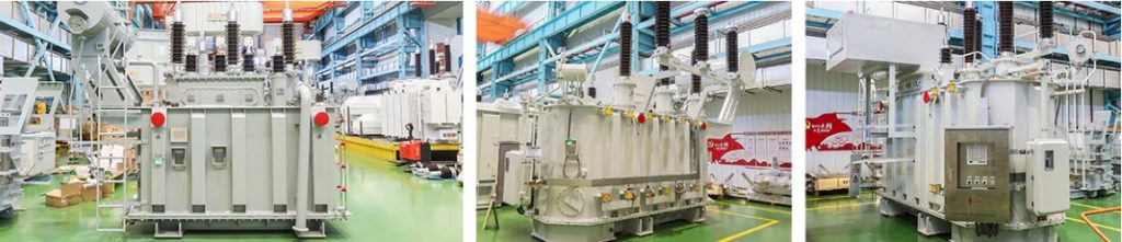
I. Product Overview
The 110kV oil-immersed power transformer is a core piece of equipment in power transmission and distribution systems. It is primarily used to transform high voltage of 110 kilovolts (kV) to lower voltage levels such as 35kV or 10kV, or vice-versa, enabling economical, efficient transmission and distribution of electrical energy. Renowned for its high reliability, large capacity, long service life, and mature manufacturing technology, it plays an indispensable role in national grids, regional networks, and large-scale industrial projects.
Product Model Example: SFSZ11-50000/110
- S: Three-Phase
- F: Air-Cooled
- S: Three-Winding
- Z: On-Load Tap Changer
- 11: Design Series Number (Performance level code, e.g., Type 11 indicates low-loss, energy-efficient products)
- 50000: Rated Capacity (kVA)
- 110: Rated Voltage Level on High-Voltage Side (kV)
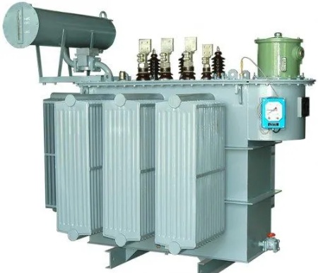
II. Main Structure
The transformer is mainly composed of the following major parts:
1. Core and Windings (Core Component)
- Core: Made from high-grade, high-permeability, cold-rolled grain-oriented silicon steel laminations, stacked using a stepped-lap (multi-step lap) process. Its function is to form the magnetic circuit, offering excellent magnetic permeability and low no-load loss.
- Windings: Comprise the high-voltage winding, medium-voltage winding (if applicable), and low-voltage winding. Typically constructed using interleaved, continuous disc, or helical types, wound from oxygen-free copper conductors, and subjected to rigorous insulation treatment. The windings form the electrical circuit of the transformer.
2. Tank and Cooling System
- Tank: Welded from steel plates, it houses the core with windings and the transformer oil, and provides mechanical support and external protection. The tank walls are fitted with cooling fins or removable radiators.
- Transformer Oil: Uses high-quality mineral oil or synthetic ester insulating oil. Main functions: Insulation, Cooling, and Arc Quenching (within the on-load tap-changer).
- Cooling Equipment: Depending on capacity, primarily uses Oil Natural Air Natural (ONAN) or Oil Forced Air Forced (OFAF) cooling. Fans force air over the radiators to accelerate oil cooling.
3. Protection System
- Conservator (Oil Expension Tank): Compensates for the expansion and contraction of the transformer oil due to temperature changes, reduces contact between oil and air, and delays oil aging. Often equipped with a diaphragm (bag or bellows) for full sealing.
- Breather (Dehydrating Breather): Contains silica gel desiccant to absorb moisture from the air entering the conservator, keeping the oil dry.
- Buchholz Relay (Gas Relay): Installed in the pipe between the main tank and the conservator. It activates an alarm or trips the circuit breaker in case of minor internal faults generating gas or sudden, violent oil surges.
- Pressure Relief Device: Rapidly opens to relieve internal pressure in case of a serious fault, preventing tank rupture.
- Sudden Pressure Relay (Optional): Provides further protection by limiting pressure rise due to internal arcing faults.
- Temperature Indicator: Monitors the top oil temperature, providing remote signals and local reading.
4. Bushings
- High-Voltage Bushing: Safely brings the high-voltage leads from the internal windings out through the tank. The 110kV level typically uses oil-impregnated paper capacitor bushings, which offer excellent electric field grading and insulation performance.
- Medium/Low-Voltage Bushings: Bring out the leads from the medium and low-voltage windings.
5. Tap Changer
- Off-Circuit Tap Changer (DETC): Allows tap position changes only when the transformer is disconnected from the network.
- On-Load Tap Changer (OLTC): Automatically or manually changes tap positions while the transformer is energized and under load, to stabilize the output voltage. This is a key component in modern smart grids.
III. Working Principle
Based on the principle of electromagnetic induction. When an AC voltage is applied to the primary (high-voltage) winding, it creates an alternating magnetic flux in the core. This alternating flux links with the secondary (low-voltage) winding, inducing an electromotive force (EMF) in it. The voltage ratio is equal to the turns ratio:U1U2=N1N2U2U1=N2N1
By changing the number of turns in the winding (i.e., operating the tap changer), voltage transformation is achieved.
IV. Key Features & Advantages
- High Reliability: Mature construction, stable materials, comprehensive protection systems, design life typically exceeds 30 years.
- High Efficiency & Energy Saving: Utilizes low-loss silicon steel and advanced design, resulting in low no-load and load losses, compliant with national energy efficiency standards (e.g., GB 20052).
- Excellent Insulation Performance: The oil-paper insulation system formed by transformer oil and insulating paper possesses very high dielectric strength.
- Superior Heat Dissipation: The circulating flow of oil effectively carries away heat generated by the core and windings.
- Easy Maintenance: Equipped with various monitoring and protection devices, facilitating condition monitoring and regular maintenance.
- Strong Adaptability: Can be configured with on-load tap changers, enhanced cooling systems, etc., to suit different load demands and operating environments.
V. Main Technical Parameters
| Parameter Category | Typical Description | Remarks |
|---|---|---|
| Rated Voltage | HV Side: 110±8×1.25% / 121 kV | Indicates tap range and rated voltage |
| MV Side (if applicable): 38.5 kV | ||
| LV Side: 10.5 / 11 kV | ||
| Rated Capacity | 10,000 kVA ~ 150,000 kVA | Common capacity ratings |
| Rated Frequency | 50 Hz | Chinese Standard |
| Vector Group | YNyn0d11 or YNd11 | Common for three-winding or two-winding |
| Impedance Voltage | Approx. 10.5% ~ 18% | Depends on capacity and design |
| No-Load Loss | Meets or exceeds GB 20052 standard | e.g., Type 11 < 15 kW (for 50MVA) |
| Load Loss | Meets or exceeds GB 20052 standard | e.g., Type 11 < 220 kW (for 50MVA) |
| Sound Level | ≤ 65 dB(A) | Measured at 0.3 meters from the equipment |
| Cooling Method | ONAN / OFAF | |
| Tap Changer Type | Off-Circuit or On-Load | |
| Insulation Level | LI480 AC200 / LI325 AC140 / LI75 AC35 | HV/MV/LV Lightning Impulse/Power Frequency Withstand Voltage |
VI. Application Fields
- Regional Substations: Acts as a hub between transmission and distribution grids, stepping down 110kV to 10kV or 35kV.
- Large Industrial Plants: Such as steel, petrochemical, data centers, serving as the core equipment in the main step-down substation.
- Power Plants: Serves as a generator step-up transformer, elevating the generator output voltage to 110kV for grid connection.
- Urban Power Grid Construction & Renovation: Meets the growing power demand in urban load centers.
VII. Transportation, Installation & Maintenance
Perform periodic inspection and oil replacement for the on-load tap changer.
Transportation: Must be transported under a positive pressure of nitrogen or dry air, strictly preventing moisture ingress. Strict limits apply to the tilt angle during transport.
Installation: Must be performed by specialized personnel: positioning on foundation, oil filling, settling, vacuum pumping, hot oil cycling, etc., to ensure restoration of insulation performance.
Routine Maintenance:
Regularly check oil level, oil temperature, and breather silica gel color.
Periodically take oil samples for testing (chromatography, moisture content, dielectric strength – DGA). This is an effective method for diagnosing incipient internal faults.
Conduct regular electrical tests (winding resistance, insulation resistance, turns ratio, etc.).