


Leverandør af elektroniske komponenter | Transformere, Induktorer, Invertere


Højspændingsstrømtransformator
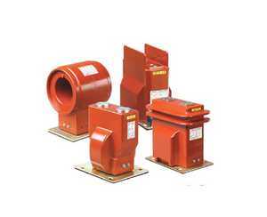
Højspændingstransformator Ferritkerne Elektrisk krafttransformator Højfrekvent strømtransformator
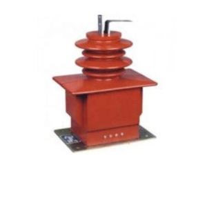
24W 12V AC/DC Justerbar Switching Power Supply High Power 200-240VAC Strømspænding Transformer Strømadapter PC Materiale 1A
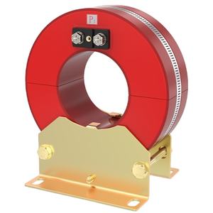
Tilpasset enfaset højstrømsisolationstransformator Lavspænding højstrømstransformerspecifikationer
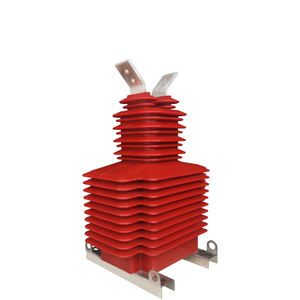
45-6800kVA 12kV 15kV 24kV 36kV Customized Input UL-certificeret High Power Pad-Mounted Power Transformer Kompakt understation
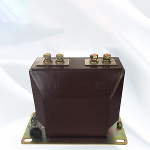
China High Voltage Current 110 Volt 220 Volt 12V DC 240V AC Converter Transformers Switching SMPS Transformers
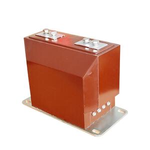
CE/ISO-godkendt afskærmet enfaset isolationstransformer med støjimmunitet 110V/220V/380V udgangsspændingsmuligheder
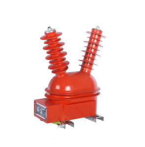
11kV højspændings trefaset nulsekvens CT-strømtransformer med 50Hz frekvens

400 Kva 500kva 630 Kva 1500 Kva Input Output 50/60Hz Trefaset Oil Immersed Distribution Transformer
Højspænding Elektrisk AC/DC 24v-36v Switching Power Supply 1,2A-2A High Current Transformer 32Volt 2Amp
24kV højspændingsstrømsensor Rogowski-spole Fleksibel probe toroidal strømtransformer
S11/S13 fuld serie 50-5000KVA højspændings trefasede transformere Små højspændingsstrømtransformatorer
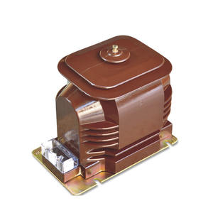
Indendørs/udendørs højspændingsstrømtransformer &Spændings transformer, Potential Transformer CT, PT
Oversigt over højspændingsstrømtransformer
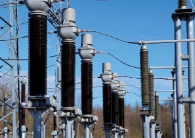
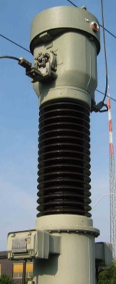
Højspændingsstrømtransformatorer (CT'er) er væsentlige instrument transformere bruges i elektriske strømsystemer til at måle og overvåge høje strømme sikkert. De konverterer høje strømniveauer i transmissionsledninger til proportionelle lavstrømssignaler der kan bruges af meter, beskyttelsesrelæer, og overvågningsudstyr.
Disse transformere er meget udbredt i kraftværker, elektriske transformerstationer, og højspændingstransmissionsnet, sikring af nøjagtig strømmåling og pålidelig beskyttelse af strømsystemudstyr.
Sådan fungerer højspændingsstrømtransformere
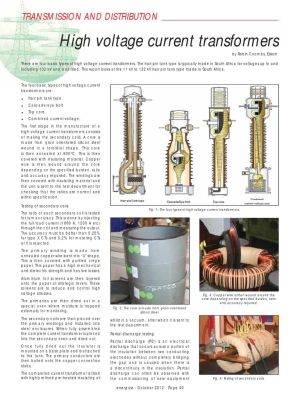
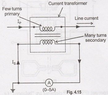
High-Voltage Current Transformers
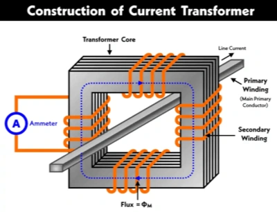
Højspændingsstrømtransformatorer (CT'er) operate based on the principle of elektromagnetisk induktion, converting large primary currents in high-voltage power systems into smaller, standardized secondary currents that can be safely measured and monitored.
The current transformer provides electrical isolation between the high-voltage primary circuit and the low-voltage measurement and protection equipment. It is therefore an important component in power-system måling, overvågning, kontrollere, og beskyttelse.
| Komponent | Fungere |
|---|---|
| Primær dirigent | Carries the high current from the power system and generates the primary magnetic field. |
| Magnetisk kerne | Provides a low-reluctance path for magnetic flux and improves electromagnetic coupling between the primary and secondary circuits. |
| Sekundær vikling | Produces a reduced current proportional to the primary current for measurement and protection purposes. |
| Isoleringssystem | Provides electrical insulation between high-voltage conductors and grounded or low-voltage components. |
| Beskyttende boliger | Protects the internal components from mechanical damage, fugtighed, støv, og miljøforhold. |
| Terminal / Connection System | Provides reliable electrical connections between the secondary winding and external measuring or protection equipment. |
| Shielding and Grounding Components | Help control electric-field distribution and improve operational safety and insulation performance. |
Operating Principle
When an alternating current flows through the primary conductor, it produces an alternating magnetic flux in the magnetic core. According to Faraday's law of electromagnetic induction, this changing magnetic flux induces a voltage in the secondary winding.
Under normal operating conditions, the secondary current is approximately proportional to the primary current according to the transformer turns ratio:
where:
- = primary current
- = secondary current
- = number of primary turns
- = number of secondary turns
F.eks, a CT rated 1000/5 EN is designed to produce approximately 5 A of secondary current when the primary current is 1000 EN.
Standard Secondary Output
Den typiske sekundære strømudgang er 1 A or 5 EN, allowing conventional measuring instruments, beskyttelsesrelæer, meter, and monitoring devices to process high primary currents without being directly connected to the high-current circuit.
Compared with 5 A systems, 1 A secondary CTs can reduce transmission losses and voltage drop in long secondary wiring, making them particularly useful where the distance between the CT and monitoring equipment is relatively large.
Main Applications
High-voltage current transformers are widely used in:
- Power-system current measurement
- Overcurrent and short-circuit protection
- Differential protection
- Transformer protection
- Busbar protection
- Energy metering
- Substation monitoring and automation
- Grid fault detection and analysis
Depending on the application, CTs can be designed with different accuracy classes and characteristics. Metering CTs emphasize measurement accuracy over the normal operating range, while protection CTs are designed to maintain suitable performance during high fault currents.
Key Performance Parameters
Important specifications of a high-voltage CT typically include:
| Parameter | Beskrivelse |
|---|---|
| Rated Primary Current | The primary current for which the CT is designed. |
| Rated Secondary Current | Som regel 1 A or 5 EN. |
| Transformation Ratio | Defines the relationship between primary and secondary current. |
| Nøjagtighedsklasse | Indicates the allowable measurement error under specified conditions. |
| Rated Burden | The load that can be connected to the secondary while maintaining specified performance. |
| Isoleringsniveau | Defines the CT's ability to withstand specified voltage and transient stresses. |
| Frekvens | Usually designed for the power-system operating frequency, som f.eks 50 eller 60 Hz. |
| Short-Time Thermal Current | The maximum fault current the CT can withstand for a specified short duration. |
| Rated Dynamic Current | Indicates the CT's ability to withstand the mechanical forces associated with high fault currents. |
Safety Consideration
One of the most important characteristics of a current transformer is that its secondary circuit should not normally be left open while current is flowing in the primary circuit. An open secondary can result in a dangerously high secondary voltage and may cause insulation failure, equipment damage, or electric shock.
For this reason, CT secondary circuits are normally connected to an appropriate measuring or protection circuit, og shorting terminals or test blocks are commonly provided for maintenance and testing.
Oversigt
In modern high-voltage power systems, current transformers serve as an important interface between high-current power circuits and low-level measurement and protection systems. By using electromagnetic induction, they provide accurate current transformation, electrical isolation, and compatibility with standardized protection and monitoring equipment. Their performance depends not only on the transformation ratio but also on core design, insulation structure, accuracy class, burden, saturation characteristics, and short-circuit withstand capability.t output is 1A eller 5A, som sikkert kan måles af overvågningsanordninger.
Typer af højspændingsstrømtransformatorer
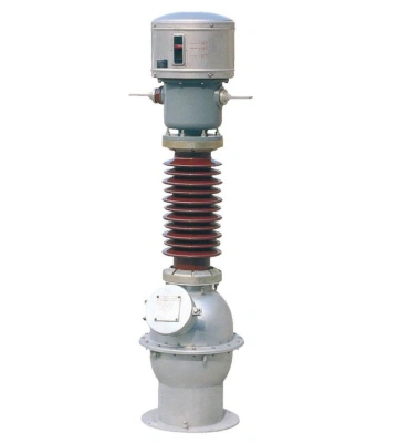
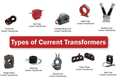
- Olie-nedsænket strømtransformer – Anvendes i udendørs højspændingsstationer.
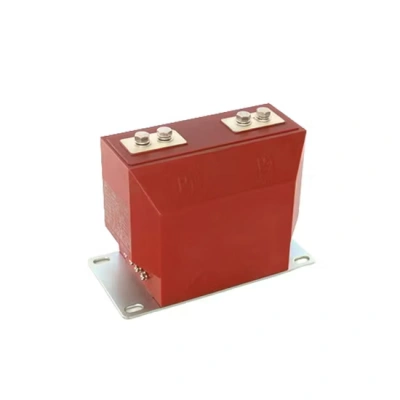
- Støbt harpiks strømtransformer – Velegnet til indendørs koblingsanlæg.
- Ring Type Strømtransformer – Installeret omkring ledere til måling.
- Udendørs Instrument Transformer – Designet til højspændingstransmissionsnetværk.
Fordele ved højspændingsstrømtransformere
- Nøjagtig strømmåling til overvågning af elsystemet
- Forbedret beskyttelse til elektrisk udstyr og kredsløb
- Høj isoleringsstyrke til højspændingsapplikationer
- Pålidelig drift i transformerstationer og transmissionssystemer
- Kompakt og holdbart design
Virksomhedsprofil
Luoyang Datang Energy Technology Co., Ltd. er en højteknologisk virksomhed, der integrerer R&D, fremstilling, og levering af strømudstyr og vedvarende energiløsninger. Specialiseret i transformatorer, nye energikomponenter, fordelingsskabe, og invertere, vi har udvidet vores portefølje til at omfatte solcelleanlæg, energilagringsløsninger, og luftvarmepumper. Med teknologisk innovation som vores kerne, vi fokuserer på at skabe høj-pålidelighed og højtydende kraft- og energieffektivitetsløsninger til at betjene globale kunder. Gennem et strengt kvalitetskontrolsystem og international standard certificering, vi leverer konstant fremragende produkter, der giver vores kunder mulighed for at bygge sikkert, stabil, og bæredygtige elsystemer.
Hvis du vil have en høj kvalitet, højspændingsstrømtransformer leverandør, vi inviterer dig til at kontakte os eller forespørge om relaterede produkter.
Betalingsmetoder tilHøj-Spændingsstrømtransformator
L/C, T/T, Western Union, Paypal, Kreditkort osv.
Forsendelse afHøj-Spændingsstrømtransformator
Når betalingen er modtaget, til søs, luft, eller udtrykke hurtigst muligt.
Ofte stillede spørgsmål om højspændingsstrømtransformer
1. Hvad er en strømtransformator (CT)?
A current transformer (CT) is an instrument transformer designed to convert high primary currents into smaller, standardized secondary currents for safe measurement, overvågning, og beskyttelse.
CTs provide electrical isolation between the high-voltage power circuit and low-voltage measuring or protection equipment, allowing meters and protective relays to monitor system current without being directly connected to the high-current conductor.
2. How does a high-voltage current transformer work?
A high-voltage CT operates according to the principle of elektromagnetisk induktion. When alternating current flows through the primary conductor, it generates a changing magnetic flux in the CT core.
This changing magnetic flux induces a current in the secondary winding. The secondary current is proportional to the primary current according to the transformer's turns ratio.
F.eks, -en 1000/5 A CT produces approximately 5 A of secondary current when the primary current reaches 1000 EN.
3. Hvor bruges højspændings-CT'er?
High-voltage current transformers are commonly installed in:
- Electrical substations
- Power generation plants
- Transmission and distribution systems
- High-voltage switchgear
- Transformer protection systems
- Industrial power networks
- Grid monitoring and automation systems
They can be used for both continuous current measurement og fault-current detection.
4. Hvad er standard sekundærstrøm for en CT?
The most common standardized secondary current ratings are 1 A and 5 EN.
EN 5 A secondary output has traditionally been widely used in conventional protection and metering systems. EN 1 A secondary output can be advantageous when the CT is installed far from the measuring or protection equipment because it can reduce losses and voltage drop in the secondary wiring.
The appropriate secondary rating should be selected according to the connected equipment and system design.
5. What does a CT ratio mean?
The CT ratio describes the relationship between the rated primary current and the rated secondary current.
F.eks:
- 200/5 EN → 200 A primary corresponds to 5 A secondary
- 600/5 EN → 600 A primary corresponds to 5 A secondary
- 1000/1 EN → 1000 A primary corresponds to 1 A secondary
Selecting the appropriate ratio is important for achieving accurate measurement and ensuring that protection equipment operates correctly.
6. Hvorfor er CT'er vigtige i strømsystemer?
CTs allow high currents in electrical networks to be measured without directly connecting measurement instruments to high-current conductors.
They are important because they provide:
- Current measurement
- Elektrisk isolation
- Fault detection
- Overcurrent protection
- Energy metering
- System monitoring
- Protection relay inputs
Som et resultat, CTs play an important role in maintaining the pålidelighed, sikkerhed, and controllability of high-voltage electrical systems.
7. Can high-voltage CTs be used for protection relays?
Ja. Current transformers are widely used with beskyttelsesrelæer.
During abnormal conditions such as short circuits or severe overloads, the CT provides a current signal to the protection relay. The relay analyzes the signal and can initiate the appropriate circuit-breaker operation to isolate the fault.
Protection CTs are generally designed with characteristics suitable for maintaining reliable performance during high fault currents.
8. What is the difference between metering CTs and protection CTs?
Metering CTs and protection CTs are designed for different purposes.
Metering CTs are optimized for high accuracy within their specified measurement range and are commonly connected to electricity meters and monitoring instruments.
Protection CTs are designed to provide an appropriate current signal to protective relays, particularly during fault conditions when the primary current can become many times higher than its normal operating value.
The selection between the two depends on the intended application and the requirements of the electrical protection or measurement system.
9. What is CT accuracy class?
The accuracy class indicates the allowable measurement error of a CT under specified operating conditions.
For metering applications, accuracy is particularly important because even small measurement errors can affect energy measurement and billing.
For protection applications, the CT's ability to reproduce current accurately during high fault conditions and avoid excessive saturation is particularly important.
The appropriate accuracy class should therefore be selected according to the requirements of the connected equipment and applicable standards.
10. What is CT burden?
CT burden refers to the load connected to the CT secondary circuit, generally expressed in VA at a specified power factor.
The burden can include:
- Protective relays
- Measuring instruments
- Meters
- Test equipment
- Secondary wiring
If the connected burden exceeds the CT's rated capability, measurement accuracy and protection performance may be affected. Derfor, the CT should be selected with a suitable burden rating for the complete secondary circuit.