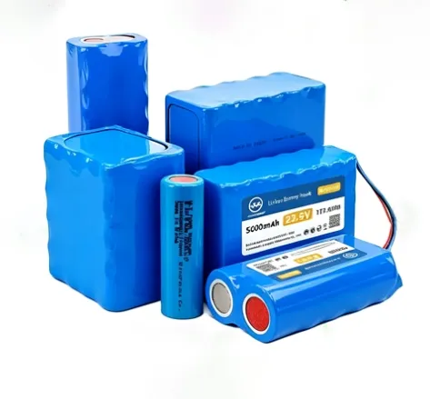
Product Overview
Custom modules are for buyers whose voltage, capacity, mechanical envelope or communication protocol does not match a catalogue product. The scope is not “any battery you want” — it is a defined set of configurable variables, each with a different impact on MOQ, NRE and lead time. The practical starting point is distinguishing what can change on an existing platform versus what requires new tooling or firmware development.
Voltage and capacity are the easiest changes; cell choice drives cost and cycle life. Enclosure and connector changes drive tooling. Label and branding changes do not. A project that stays within a standard enclosure, standard BMS and standard firmware carries low or no tooling cost and a lower MOQ threshold; a new injection-moulded enclosure or new BMS firmware pushes MOQ toward 500–1,000 units with NRE quoted separately.
Key Features
- Configurable voltage and capacity. Custom pack voltage commonly spans 3.7 V to 100 V, with LFP modules available in 12 V / 24 V / 48 V / 60 V / 72 V / 96 V classes and capacities from 5 Ah to 1,000 Ah depending on cell format.
- BMS scope is the main technical differentiator. Options range from a basic protection board to a smart BMS with CAN (CAN 2.0B, CANopen, J1939), RS485 (MODBUS RTU), UART, SMBus or I²C, fuel gauge and active balancing.
- Enclosure and connector are tooling decisions. ABS, aluminium or IP-rated enclosures (IP65–IP67) and custom connectors/harnesses are available, but new enclosure geometry triggers tooling and raises MOQ.
- Certification is scoped to the module, not the cell. UN38.3 for transport is near-universal; IEC 62133-2 for rechargeable cells/batteries and UL 2054 for pack-level North American safety are the common add-ons depending on market and application.
- Prototype-to-production path exists. One-off and engineering samples are feasible; A-samples ~2 weeks, B-samples ~3–4 weeks, C-samples (MP-equivalent) 4–6 weeks, with 1–3 weeks added for new tooling.
Technical Specifications — What Can Be Customized
Variable | Range / Options | Impact on MOQ & Lead Time |
|---|
Voltage | 3.7–100 V; LFP 12/24/48/60/72/96 V classes | Low — configuration change on existing platform |
Capacity | 5–1,000 Ah (cell-format dependent) | Low to moderate — cell count and assembly time |
Cell chemistry | LFP / NMC / LTO / LiPo / primary lithium | Moderate — cell sourcing and cycle-life trade-off |
BMS function | Protection only → smart BMS with CAN/RS485/UART/SMBus, fuel gauge, balancing | Moderate to high — firmware development adds NRE |
Enclosure | Heat-shrink / standard case / custom injection-moulded / aluminium / IP65–IP67 | High — new tooling, MOQ 500–1,000 for new moulds |
Connector / harness | Custom connector type, cable length, routing | Low to moderate — tooling only if non-standard |
Label / branding | Logo, label artwork, packaging | Low — lowest MOQ threshold |
Certification | UN38.3 / IEC 62133-2 / UL 2054 / IEC 62619 / UL 1973 | Certification run adds cost and time, not unit price |
Caveat: The table describes the customization envelope, not a guarantee that every combination is available at the lowest MOQ. Each variable interacts — a new enclosure paired with new BMS firmware is a substantially larger NRE scope than either change alone.
Typical Applications
Application | Why custom fits |
|---|
Medical devices | Fixed mechanical envelope, IEC 62133-2 / UL 2054 scope, traceability and redundant protection requirements |
Industrial equipment / robotics | Voltage and connector matched to the host machine; vibration and ingress protection specified to the environment |
Portable power / outdoor equipment | Enclosure form factor and IP rating driven by the product housing, not a catalogue case |
Legacy or replacement packs | Match an existing electrical and mechanical interface when the original pack is obsolete or supplier-locked |
OEM private-label programmes | Standard platform with custom label, connector and firmware adaptation at lower MOQ than full new tooling |
Installation & Maintenance Notes
Installation
- Confirm the BMS protocol against the host device before sign-off. The most common custom-pack failure is a communication mismatch — the pack protects correctly but the host cannot read it. Send the target protocol or host device for verification early.
- Do not assume lithium-equivalent terminal torque on a custom enclosure. Torque value comes from the specific mechanical design; a custom terminal block may have a lower rating than a standard M6/M8 hardware assumption.
- Verify charger compatibility with the custom BMS. A custom pack is only as reliable as the charger paired with it; charging profile and communication must match.
Maintenance
- BMS log review: monthly. For custom packs, the BMS data is the only standard diagnostic channel — cell voltage spread, temperature and fault history should be reviewed against the agreed protection thresholds.
- Terminal and connection inspection: every 6–12 months. Custom connector and harness designs have less field history than standard formats; torque and visual checks should not be skipped on the assumption that a new design is “maintenance-free.”
- Documentation retention: keep the approved cell specification, BMS function description, protection threshold logic, enclosure/insulation details and test records — these are the evidence set for warranty and repeat orders.