Product Categories

Pouch Battery Cells

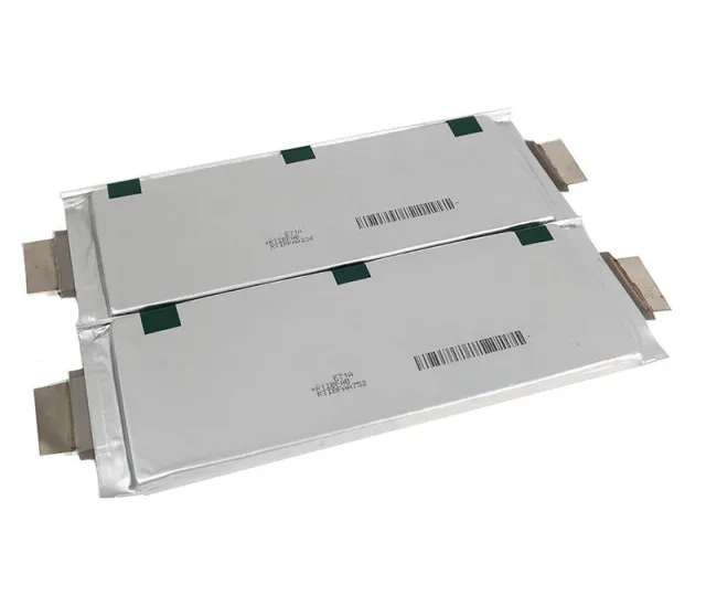
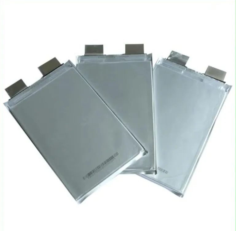
Pouch cells seal the electrode stack in an aluminum-laminate film (polyamide/aluminum/polypropylene) rather than a rigid metal can.
Pouch Battery Cells

Products in Pouch Battery Cells

Product Overview

Pouch cells seal the electrode stack in an aluminum-laminate film (polyamide/aluminum/polypropylene) rather than a rigid metal can. This format delivers the highest gravimetric energy density among mainstream lithium-ion cell types and allows flexible dimensional customization, but it removes the structural rigidity that prismatic and cylindrical cans provide. The pouch is a packaging choice, not a structural component: compression, dimensional control, and thermal-runaway propagation protection must be engineered at module level, not assumed from the cell. Cells are supplied as components; backing plates, gap pads, and BMS integration are implemented in the module.

Key Features

  • Gravimetric density leads the class, volumetric density does not automatically follow. Commercial NMC pouch cells reach ~340 Wh/kg and ~700 Wh/L on a balanced power-energy design (72 Ah, 3C continuous). Anode-free NMC pouch cells are specified at 525 Wh/kg in 6.3 Ah format; semi-solid-state pouch cells are in the 300–360 Wh/kg range at cell level. The foil package is light, but the large footprint can constrain volumetric packing at pack level.
  • Compression is a specification, not a suggestion. The optimal initial compression for long cell life is 0.05–0.5 MPa, and the pressure evolves upward by up to 10× the initial value as the cell expands during charge and aging. Module design must avoid local stress concentrations and allow volumetric expansion — typically through gap pads — or the compression that protects against delamination becomes the compression that accelerates aging.
  • The large surface area is a thermal advantage for high-rate duty. Pouch cells dissipate heat more effectively than dense cylindrical formats through their broad face, which is directly relevant to eVTOL and high-discharge applications where sustained current is the sizing constraint. The trade-off: slim, large-footprint cells require larger backing plates to apply uniform pressure, which reduces pack-level volumetric efficiency.
  • Gas generation and swelling are continuous degradation mechanisms, not just abuse events. At 40°C, pouch cells have been observed to increase in volume by up to 20 ml in one day under elevated-voltage storage, and degassing-and-repair testing showed capacity recovery after gas release, confirming gas generation as an ongoing degradation pathway during cycling. Pouch cells are structurally more susceptible to swelling and dimensional change than rigid formats.
  • Size flexibility is a real advantage — and a sourcing variable. Pouch cells can be built in customized dimensions for thin or space-constrained envelopes, but this flexibility means footprint, tab position, and capacity are not standardized across suppliers. Module and pack designs that depend on pouch cells must be validated against the specific cell drawing, not a generic format assumption.

Technical Specifications

Typical cell-level ranges. Exact values vary by chemistry, supplier, and test condition; confirm against the specific datasheet and drawing before design lock.

Parameter

Typical Range / Value

Chemistry

NMC / NCA dominant; LFP pouch available for lower-energy, longer-cycle niches

Nominal voltage

3.6–3.7 V (NMC/NCA); 3.2 V (LFP pouch)

Capacity

5–72 Ah commercial; 20–50 Ah common for EV/eVTOL; custom sizes available

Gravimetric energy density

~340 Wh/kg (commercial NMC, balanced power/energy); 300–360 Wh/kg semi-solid-state; 525 Wh/kg anode-free NMC demonstrated

Volumetric energy density

~700 Wh/L (commercial NMC); higher for energy-optimised designs

Continuous discharge

3C typical on balanced designs; 5–10C on power-optimised variants

Cycle life (to 80%)

500–1,000 cycles commercial NMC pouch (condition-dependent); lower than prismatic equivalents at the same chemistry due to mechanical and gassing constraints

Initial compression

0.05–0.5 MPa recommended for long life; module must accommodate up to 10× pressure rise from expansion

Packaging

Aluminum-laminate film (polyamide/Al/PP); tabs ultrasonically or laser-welded to current collectors

Certifications (confirm per batch)

UN38.3 (transport); IEC62619 / IEC62133 where claimed; pouch format itself does not determine certification — the specific cell must be listed

Typical Applications

  • eVTOL & electric aviation — highest gravimetric density plus large-area heat dissipation for high discharge currents; 24S NCM pouch packs have been flight-demonstrated
  • High-end passenger EV & performance vehicles — thin profile and flexible footprint suit low-floor and space-constrained pack architectures
  • Drones & unmanned systems — custom dimensions and high energy density in weight-critical envelopes
  • Wearable & compact electronics — thin, shape-conforming cells where rigid cans cannot fit
  • Medical devices & specialty industrial equipment — custom pouch sizes for non-standard cavities
  • Selected ESS niches — where footprint or weight is binding and cycle-life requirements are moderate; LFP prismatic remains the default for high-cycle stationary storage

Installation & Maintenance Notes

  • Compression fixture is mandatory. Pouch cells cannot be stacked or installed without a backing plate / fixture that applies uniform pressure across the full face. Uneven pressure causes delamination and capacity loss. Torque fixtures in a cross-pattern and verify pressure distribution, not just average force.
  • Design for expansion, not against it. The module must allow the cell to breathe — volume change during charge and aging — while maintaining preload. Gap pads are the standard solution; a rigidly over-constrained stack converts normal expansion into damaging local stress.
  • Isolate cell edges and plan for venting. The cut edge of the aluminum-laminate film exposes foil; edges are typically bent over for isolation. Module trays should also guide venting gas in the event the pouch opens under overpressure.
  • Storage: moderate SOC, controlled temperature, low humidity. Elevated temperature accelerates gas generation and swelling; do not store at high SOC at elevated temperature for extended periods.
  • Do not substitute pouch cells by capacity alone. Footprint, tab position, and compression requirements differ between suppliers even at the same Ah rating. A replacement that fits the cavity may not fit the fixture.

FAQs

Is pouch format always the lightest choice for a given chemistry?

At cell level, yes—the aluminum-laminate package is lighter than a steel or aluminum can. At pack level, the comparison can invert: pouch cells require backing plates, fixtures, and gap pads that add mass and volume, while prismatic and cylindrical formats provide part of that structure themselves. Specify energy density at the pack level, not the cell datasheet level.

Can I skip compression if the cells are mechanically supported by the enclosure?

No. “Supported” is not the same as “uniformly compressed.” Pouch cells require controlled pressure across the active area to prevent delamination; enclosure walls alone do not provide that. 0.05–0.5 MPa initial compression is the reference range, and the fixture must accommodate expansion without over-constraining the stack.

What cycle life should I expect from a commercial NMC pouch cell?

500–1,000 cycles to 80% is a realistic commercial range, but it is condition-bound: temperature, C-rate, depth of discharge, and compression management all move the number materially. Do not compare a pouch cycle-life figure against a prismatic figure without matching those conditions. If the application needs 3,000+ cycles, LFP prismatic is the more defensible starting point.

What is the most common procurement error with pouch cells?

Specifying capacity and energy density first, and compression/fixture design last. A 340 Wh/kg pouch cell in a module without validated pressure distribution will lose capacity through delamination before it delivers its density advantage. The defensible sequence is application duty → compression and expansion envelope → tab/footprint drawing → energy density → cycle-life test condition → certification.

Discuss Your Project

Share your product requirements, estimated order quantity, and target delivery destination.

Send Your Inquiry Today

Tell us about your application and requirements. Our team will review your request.