
Articles
What Are Prismatic LFP Battery Cells? A Clear Guide to LiFePO4 Prismatic Cells
What are prismatic LFP battery cells? Explore LiFePO4 prismatic cell structure, key specs, cycle life, applications, and selection tips for energy storage projects.
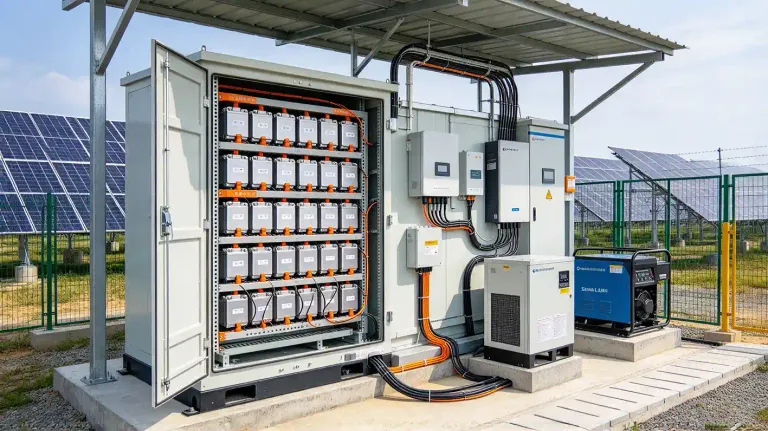
A battery cell is the smallest electrochemical unit that actually stores energy. Everything else in a battery system—modules, racks, containers, PCS—exists to connect, protect, cool, and manage cells. Among the cell formats used in stationary storage today, prismatic LFP battery cells sit at the center of attention: a hard-shell rectangular format paired with a lithium iron phosphate cathode.
That pairing is not accidental. The prismatic format makes efficient use of enclosure space and supports larger single-cell capacities; the LFP chemistry brings thermal stability and long cycle life that align well with daily cycling in solar and commercial storage. Together, they have become the default building block for many LiFePO4 prismatic cells deployed in residential, C&I, and utility-scale systems.
This guide walks through what these cells are, how they are structured and how they work, which specifications actually matter, where the chemistry helps and where it does not, and how buyers can evaluate prismatic LFP battery cells without getting lost in datasheet language.
1. What Is a Prismatic LFP Battery Cell?
1.1 The term, decoded
A prismatic LFP battery cell carries two independent pieces of information in its name.
Prismatic — rectangular, hard-shell physical format; classification: cell form factor |
LFP — lithium iron phosphate cathode chemistry (LiFePO₄); classification: battery chemistry |
Battery cell — the smallest independent electrochemical storage unit; classification: functional unit |
Prismatic describes the shape. LFP describes the chemistry. A prismatic cell can use NMC, LFP, or sodium-ion chemistry; an LFP cell can be prismatic, cylindrical, or pouch. Confusing the two is one of the most common sourcing mistakes—buyers compare “prismatic vs. LFP” as if they were alternatives, when they are dimensions on different axes.
1.2 Cell, module, and the boundary of responsibility
A prismatic LFP cell is not a plug-and-play battery. It delivers a fixed nominal voltage and rated capacity, but it needs a module structure, a BMS, thermal management, and system-level integration before it can serve a load.
Battery cell: independent electrochemical unit |
Battery module: assembly of multiple cells |
Cell output: basic voltage and capacity |
Module output: higher voltage / capacity combination |
Cell integration: must be configured into a system |
Module integration: a building block of a pack or rack |
Typical cell supplier: cell manufacturer |
Typical module supplier: module assembler / integrator |
For a full comparison of where cell responsibility ends and module responsibility begins, see our article Battery Cells vs. Battery Modules for Energy Storage: Which Is Right for Your Project?
2. Structure and Chemistry of Prismatic LFP Battery Cells
2.1 Inside the hard shell
A prismatic LFP cell is a layered electrochemical stack compressed into a rectangular aluminum or aluminum-alloy casing. The stack repeats four functional layers—cathode, separator, anode, separator—wound or stacked, then sealed with electrolyte and terminals.
Prismatic casing — aluminum hard shell; mechanical protection and compression |
Cathode — lithium iron phosphate (LiFePO₄) coated on aluminum current collector |
Anode — graphite coated on copper current collector |
Separator — porous polymer membrane; prevents short circuits while allowing Li-ion transport |
Electrolyte — lithium salt in organic solvent; ion-conducting medium |
Current collectors — Al foil (cathode), Cu foil (anode) |
Terminals & safety features — positive/negative posts, vent, overcharge safety mechanisms |
2.2 What LFP chemistry changes
The cathode is where LFP diverges from NMC. Lithium iron phosphate uses an olivine crystal framework with strong P–O covalent bonds. That bonding is the root of LFP’s thermal stability: the cathode releases oxygen far less readily than layered nickel-rich oxides, so the cell is harder to push into thermal runaway through cathode-side decomposition.
Full name: Lithium iron phosphate |
Chemical formula: LiFePO₄ |
Cathode material: Lithium iron phosphate |
Typical nominal voltage: 3.2 V |
Key characteristics: Thermal stability; long cycle life; cobalt-free cathode |
Common applications: Stationary ESS, backup power, commercial EVs, solar storage |
The trade-off is energy density. NMC delivers roughly 150% of LFP’s gravimetric energy density per unit mass, and LFP packs are about one-fifth lower in Wh/kg and one-third lower in Wh/L than NMC packs at the system level. For stationary storage, where floor space and enclosure weight are less constrained than in a passenger EV, that trade-off is often acceptable—sometimes preferable.
2.3 Why the prismatic format matters
The rectangular format is not merely cosmetic. A prismatic cell stacks neatly into a module with minimal void space between cells; a cylindrical cell leaves curved gaps that must be managed with potting or spacers. Larger prismatic cells also reduce the number of cells and interconnects per kWh—a 314 Ah cell replaces roughly three 100 Ah cells, cutting busbar joints and assembly labor.
But form factor alone does not guarantee a spatial advantage. Whether prismatic saves volume depends on cell dimensions, module compression strategy, and cooling-channel design. A poorly designed prismatic module can waste as much space as a cylindrical pack.
3. How Do Prismatic LiFePO4 Cells Work?
3.1 Charging
An external voltage drives lithium ions out of the LiFePO₄ cathode lattice. The ions cross the electrolyte, pass through the separator, and intercalate into the graphite anode. Electrons travel through the external circuit to balance charge. Energy is stored in the anode’s lithiated state.
3.2 Discharging
The process reverses. Lithium ions leave the graphite, cross back through the separator, and return to the cathode. Electrons flow through the external load—an inverter, a DC bus, or a backup circuit—delivering power.
3.3 Connecting multiple cells
A single 3.2 V cell cannot serve a 1,000 V DC bus. Cells are configured in series to raise voltage, in parallel to raise capacity and current capability, and in series–parallel to meet both requirements. At the module level, the quality of that configuration depends heavily on cell-to-cell consistency: variations in internal resistance and contact resistance between prismatic LFP cells are a primary driver of temperature imbalance in parallel-connected modules, which in turn accelerates local aging.
4. Key Specifications of Prismatic LFP Battery Cells
4.1 Voltage: nominal is not a fixed operating window
The 3.2 V LiFePO₄ battery cell is a nominal figure, not a universal charge or discharge limit. Charge cut-off often sits near 3.65 V, while discharge cut-off is set by the manufacturer—commonly between 2.5 V and 2.8 V depending on the intended cycle life and rate capability. Buyers who compare cells by nominal voltage alone miss the operating window that actually determines usable energy and BMS configuration.
Nominal voltage: 3.2 V — reference voltage for energy calculation |
Rated capacity: Ah — charge the cell can hold under specified conditions |
Rated energy: Wh — nominal voltage × rated capacity |
Charge cut-off: manufacturer-specified — upper voltage limit; affects cycle life and safety |
Discharge cut-off: manufacturer-specified — lower voltage limit; affects usable capacity |
4.2 Capacity, energy, and a worked example
Capacity in Ah describes charge; energy in Wh describes actual storage. The conversion is:
Energy (Wh) = Nominal voltage (V) × Rated capacity (Ah)
Consider a 105 Ah 3.2 V prismatic LFP cell. The nominal energy is:
3.2 V × 105 Ah = 336 Wh
That cell weighs approximately 1.98 kg, giving a gravimetric energy density of roughly 169 Wh/kg at the cell level. Dimensions are typically in the range of 200 × 130 × 36 mm, though exact figures vary by manufacturer and generation. This calculation matters because ESS proposals are priced and sized in kWh, not Ah—and the cell-level Wh figure is the starting point for every module and rack calculation.
4.3 Dimensions, weight, and system consequences
Length, width, height, and cell weight are not packaging details. They determine module compression hardware, enclosure internal dimensions, cooling-plate spacing, and even transportation classification. A cell that is 3 mm taller may force a redesign of a module cover; a cell that is 100 g heavier per unit multiplies into tons at the container level.
4.4 Charge and discharge performance: continuous vs. peak
Datasheets often list multiple current figures. They are not interchangeable.
Max continuous charge current: sustained charge rate the cell tolerates — ask: what C-rate is assumed? |
Max continuous discharge current: sustained discharge rate — ask: at what temperature and SOC window? |
Peak discharge current: short-duration surge capability — ask: for how many seconds, and at what SOC? |
C-rate: current normalized to capacity — ask: is the rating at cell or system level? |
A cell rated for 3C peak discharge for 10 seconds is not a 3C continuous cell. Treating a peak rating as a continuous rating is a common cause of accelerated degradation and BMS protection trips.
4.5 Cycle life: the number without test conditions is marketing
Published cycle-life figures for LFP prismatic cells range widely—5,000 cycles for a 105 Ah cell tested at 25°C, 0.5C/0.5C to 80% state of health; 6,000 cycles at 25°C and 0.5C with 80% depth of discharge; and over 12,000 cycles for newer large-format ESS cells under unspecified ESS-oriented conditions. These numbers are not directly comparable.
Cycle life depends on depth of discharge, charge and discharge rate, operating temperature, cut-off voltages, and the capacity-retention threshold used to define “end of life.” A 6,000-cycle claim at 80% DOD and 25°C tells a different story from a 6,000-cycle claim at 50% DOD and 35°C. The procurement rule: ask for the test conditions before treating a cycle count as a performance guarantee.
5. Advantages and Limitations of Prismatic LFP Battery Cells
5.1 Where the chemistry and format help
Thermal stability: LFP cells show higher thermal runaway trigger temperatures and lower peak temperatures than NCM cells under comparable abuse |
Long cycle life: LFP is well suited to daily cycling; degradation is slower than high-nickel chemistries under moderate conditions |
Cobalt-free cathode: avoids cobalt supply-chain and cost exposure |
Space-efficient stacking: prismatic cells pack into modules with less void volume than cylindrical cells, when designed well |
Lower self-discharge: LFP typically self-discharges more slowly than NMC under proper storage conditions |
Scalable capacity options: available from ~50 Ah to over 1,000 Ah, allowing module designers to choose cell size around enclosure constraints |
5.2 Limitations that belong in every evaluation
Lower nominal voltage. LFP’s 3.2 V nominal versus NMC’s ~3.7 V means more cells in series for the same DC bus voltage—more interconnects and more BMS channels.
Lower energy density. LFP is heavier and bulkier per kWh than NMC at both cell and system level. For weight- or footprint-constrained projects, this is a real constraint, not a footnote.
Low-temperature charging restrictions. Charging below 0°C risks lithium plating; many LFP cells require charge inhibition or external heating below freezing, and usable capacity at −10°C can fall to roughly 50–60% of room-temperature capacity.
Thermal management is still mandatory. LFP is more thermally stable than NMC, but large-capacity prismatic cells still generate heat and require engineered cooling. Under thermal abuse, accumulated combustible gases inside an LFP system can produce severe flashover even when propagation is suppressed under mechanical abuse.
5.3 Is prismatic LFP always the right answer?
No. If the project prioritizes cycle life, thermal stability, cobalt-free chemistry, and stationary footprint tolerance, LFP prismatic is a strong default. If the project is weight-sensitive, volume-constrained, or operates in sustained sub-zero charging conditions, NMC or a heated LFP architecture may deserve closer comparison. The right question is not “Is LFP better?” but “Does this chemistry–format combination fit this duty cycle and this installation environment?”
6. Common Applications of Prismatic LFP Battery Cells
6.1 Residential energy storage
Rooftop solar self-consumption, time-of-use arbitrage, and home backup. The cell-level requirements are safety, predictable capacity, and compatibility with compact wall-mounted or floor-standing enclosure designs.
6.2 Commercial and industrial storage
Peak shaving, demand-charge reduction, solar shifting, and backup. C&I systems cycle daily and are often installed in spaces where fire-code clearances and maintenance access matter as much as energy density. Prismatic LFP’s thermal profile and cycle life fit this duty cycle well.
6.3 Utility-scale BESS
Grid stabilization, renewable integration, and capacity shifting. The market has moved toward larger prismatic LFP cells—314 Ah, 587 Ah, and beyond—precisely because fewer cells and interconnects per MWh reduce balance-of-system cost and integration complexity.
6.4 Backup and off-grid power
Telecom backup, UPS, and off-grid systems where reliability and standby behavior outweigh gravimetric energy density.
Residential ESS: safety, compact dimensions, consistent capacity |
C&I ESS: cycle life, thermal management compatibility, capacity |
Utility-scale BESS: scalability, cell-to-cell consistency, system-level reliability |
Backup power: standby reliability, low self-discharge, charging capability |
7. How to Select Prismatic LFP Battery Cells for Your Project
7.1 Define energy and power before opening a datasheet
Start with kWh required, kW rated power, DC bus voltage, and daily cycling profile. A 100 kWh residential system and a 1 MWh C&I system may use the same chemistry but demand entirely different cell capacities and C-rates.
7.2 Read the specification sheet as a system document
Nominal voltage and rated capacity are entry points. The selection-critical figures are dimensions, weight, continuous and peak current limits, operating temperature range, and cycle-life test conditions. A cell that meets capacity requirements but exceeds the enclosure’s height budget is not a candidate.
7.3 Consistency is a procurement criterion, not a manufacturing detail
In a parallel-connected module of prismatic LFP cells, differences in internal resistance and contact resistance drive temperature imbalances that accelerate aging in the hardest-working cells. BMS passive balancing (typically in the 50–200 mA range) is an operational safeguard, not a substitute for factory cell matching. Ask for capacity, voltage, and DC internal resistance distribution data—not just average values.
7.4 Check BMS and system compatibility
Voltage window, current limits, temperature-sensor placement, balancing strategy, and protection thresholds must match the cell’s actual operating envelope. A BMS configured for an NMC voltage window will either underutilize or overstress an LFP cell.
Pre-order checklist:
- Confirm nominal voltage, rated capacity, and rated energy.
- Verify dimensions, terminal orientation, and weight against enclosure design.
- Confirm continuous charge/discharge current and peak-current duration.
- Review cycle-life test conditions: temperature, C-rate, DOD, end-of-life threshold.
- Request cell-to-cell consistency data (capacity, OCV, DCIR).
- Confirm BMS compatibility and thermal-management assumptions.
For a deeper purchasing checklist, see our upcoming article: A Buyer’s Guide to Prismatic LFP Battery Cells: 5 Key Metrics to Check Before Ordering.
8. From Individual Cells to Complete Energy Storage Systems
A prismatic LFP cell does not become a storage system on its own. The integration chain runs:
Cell → Module → Pack / Rack → ESS
Cells provide the electrochemical storage. Modules combine cells into a mechanically compressed, electrically connected unit. Packs or racks add enclosure, busbars, and thermal hardware. The BMS monitors voltage, current, and temperature, and performs balancing and protection. The PCS converts DC power to AC for loads or the grid.
Not every ESS uses the same four-stage architecture—some designs integrate cells directly into rack-level units—but the principle holds: cell-level performance is necessary, not sufficient. System-level thermal design, contact resistance control, and BMS logic determine whether good cells deliver good system life.
Related product directions: LFP prismatic cells sit upstream of our 96V / 144V / 192V customizable LiFePO4 battery modules. For projects exploring alternative chemistries, our 24V 160Ah sodium-ion battery module and 16S1P NMC battery module illustrate how cell chemistry choices translate into module-level products. These modules are not necessarily built from the 105 Ah cell used as an example above; they are separate product lines for different application requirements.
9. Frequently Asked Questions About Prismatic LFP Battery Cells
Q1. Is a LiFePO₄ prismatic cell a lithium-ion battery?
Yes. LFP is one chemistry within the lithium-ion family, alongside NMC, LCO, LTO, and others.
Q2. What is the nominal voltage of a prismatic LFP battery cell?
Typically 3.2 V. Charge and discharge cut-off voltages are manufacturer-specific and should be taken from the datasheet, not inferred from the nominal figure.
Q3. How long do prismatic LiFePO₄ cells last?
It depends on DOD, C-rate, temperature, cut-off voltages, and the capacity-retention threshold used to define end of life. Published figures from 5,000 to over 12,000 cycles exist, but they are only comparable when the test conditions match.
Q4. Are prismatic LFP cells suitable for solar energy storage?
Yes, for many solar and ESS duty cycles. Suitability still depends on system voltage, daily energy throughput, BMS configuration, and site temperature range.
Q5. What is the difference between prismatic LFP and prismatic NMC cells?
Both are rectangular cells, but the cathode chemistry differs. LFP offers higher thermal stability and longer cycle life at lower gravimetric and volumetric energy density; NMC offers higher energy density per unit mass and volume but demands more thermal safeguards.
Conclusion
Choosing a battery cell is not a capacity contest. Chemistry, format, continuous current limits, cycle-life test conditions, low-temperature behavior, and cell-to-cell consistency all shape what a project will actually deliver over ten or fifteen years. Prismatic LFP battery cells earn their place in stationary storage because the chemistry and the format solve real problems together—thermal stability, daily-cycle durability, and space-efficient module design—but the specification details decide whether those advantages survive integration.
Looking for Prismatic LFP Battery Cells for Your Energy Storage Project?
Contact PDDN to discuss your required cell capacity, voltage window, dimensions, and application profile. Luoyang Datang Energy Tech Co., Ltd. can help you evaluate suitable battery cell options against your system architecture and duty cycle.